Description
ANSI FLANGES
Most forged steel flanges correspond to the requirements of the American Standards Association (ASME/ANSI Standard B16.5) and the ASTM Specification A-105.
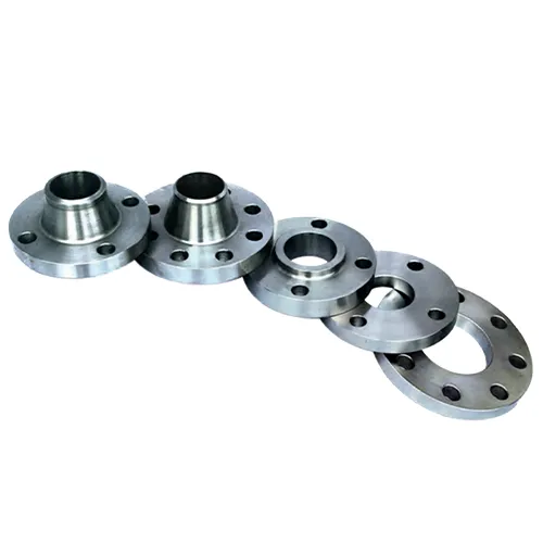
The following types are manufactured and stocked:
Welding Neck flanges, available in all pressure ratings and sizes, are butt-welded to the end of the pipe, and are usually specified when service conditions are severe and excellent workmanship necessary. Since the inside diameter of the flange must match that of the pipe, the flange bore should be specified in ordering.
Slip-on flanges, also available in most pressure ratings and sizes, are a popular type due to their ease of application. This flange slips over the end of the pipe and is usually set so that the flange face is about .375″ (9.5mm) beyond the end of the pipe. This permits double-welding of the flange – one strength fillet weld to join the hub of the flange to the pipe, and a seal fillet weld inside the flange at the end of the pipe. Where operating conditions permit, the seal weld is omitted.
Slip-on flanges are most frequently used at lower pressure – Class 150 (PN 20) or Class 300 (PN 50) primary service pressure ratings. Many pipe designers are reluctant to use slip-ons for higher pressures, since (1) the joint between the flange and pipe is not as strong as in the welding neck type; and (2) the junction of the flange and pipe is more susceptible to corrosion.
Screwed or Threaded flanges are attached to the pipe like any other screwed fittings, and may be back-welded to seal the joint between pipe and flange. Although still available in most sizes and pressure ratings, screwed fittings today are used almost exclusively in smaller pipe sizes and at low pressures.
Lap Joint or Van Stone flanges are used on piping equipped with lap joint stub ends or with lapped pipe. They may be used at all pressures and are available in a full size range. These flanges slip over the pipe, and are not welded or otherwise fastened to it; bolting pressure is transmitted to the gasket by the pressure of the flange against the back of the pipe lap.
Lap Joint flanges have certain special advantages: (1) freedom to swivel around the pipe facilitates the lining up of opposing flange bolt holes; (2) lack of contact with the fluid in the pipe often permits the use of inexpensive carbon steel flanges with corrosion resistant pipe or tubing; (3) in systems which erode or corrode quickly, the flanges may be salvaged for re-use.
Socket-welding flanges contain a recess in the back of the flange to receive the end of the pipe, which is attached by a fillet weld around the hub of the flange. Since socket-welding connections are not as strong as butt-welded joints, the use of this type of flange is almost always confined to NPS 4 (DN 100) and smaller sizes, and to the lower pressure ratings. Its chief advantage lies in the ease of preparation and installation.
Blind flanges, available in all sizes and pressure ratings, are solid forgings used to close off the end of a piping system and to gain easy access to the interior of the line.
Reducing flanges are available. Refer to page 18.
FLANGE FINISHES
The finish of contact faces of pipe flanges and connecting end flanges of fittings shall be judged by visual comparison with AARH Standards and not by instruments having stylus tracers and electronic amplification (see ANSI/ASME B46.1)
The finishes required are given below. Other finishes may be furnished upon application.
RAISED FACE AND LARGE MALE AND FEMALE: Either a serrated-concentric or serrated-spiral finish having from 45 to 55 grooves per inch (0.6 to 1mm pitch) shall be used. The cutting tool employed shall have an approximate 0.06″ (1.6mm) or larger radius. The resultant surface shall have a 125 to 250 microinch roughness.
TONGUE AND GROOVE AND SMALL MALE AND FEMALE: The gasket contact shall not exceed 125 microinch roughness.
RING JOINT: The side wall surface of gasket groove shall not exceed 63 microinch roughness.